HOW IT WORKS

The process of generating electricity with this invention involves three stages as illustrated in the diagram.

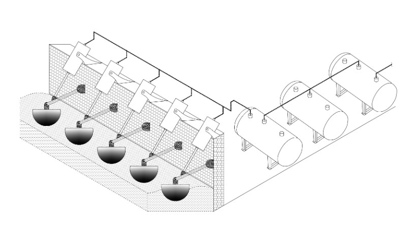
  • Generating pressurised air

    The floaters, which are positioned at sea level, capture energy from incoming waves by moving up and down with the waves. Floater's up and down movement compresses and decompresses the attached pneumatic cylinders, which produces high-pressure air. The high-pressure air is then stored in tanks.

  • Generating electricity using generated hydraulic force

    The hydraulic force is transformed into rotational motion through hydraulic motors, and electricity is produced by connecting an alternator to these hydraulic motors.

  • Generating high-pressure hydraulic force using the generated air and Buoy

    An intricately crafted buoy is constructed with an open bottom and mechanically controlled shutters on its top, enabling the retention or release of air. It will submerge in the water upon air release and regain buoyancy when the air is retained.

    A pair of hydraulic cylinders are attached to the buoys and placed on top of the liquid chamber. Upon the infusion of the generated air into the submerged buoy, it will acquire buoyancy and commence its upward motion. The vertical force exerted by the ascending buoys results in the compression of the linked hydraulic piston, producing a high-pressure hydraulic force. Upon reaching the top, the buoy releases the contained air, causing it to submerge due to increased mass. The descent rate is regulated using the low-pressure hydraulic force generated by the pneumatic motors.

    The synchronized upward and downward movement of the buoy creates a constant hydraulic force. The hydraulic flow can be increased by increasing the diameter of the hydraulic cylinder, and the pressure can be increased by increasing the volume of the buoy.

    Amplifying the hydraulic force necessitates a significant air volume, which can be naturally extracted from ocean waves.

Details Description of how it works:

how it works
  • Referring to Figure 1, The pressurized air is generated using the Floater and the connected Pneumatic Cylinder, driven by the energy of the sea waves. The pressurised air stored in the attached Air Tank is used to generates the buoyant force. This buoyant force is then transformed into hydraulic pressure within the Hydraulic Cylinder. The resulting hydraulic pressure and flow is directed into the Hydraulic Motor, where the hydraulic force is converted into rotational motion. The generated rotational motion is further converted into electric energy by the attached Alternator.

  • The embodiments of this invention consist of the following components, 1. Floater, 2. Floater Arm, 3. Static Structure, 4. Pneumatic Cylinder, 5. Pneumatic Cylinder Piston Rod, 6. Non- Return Air Suction Valve, 7. Pneumatic Outlet, 8. Pressurized Air Rail, 9. Air Tank, 10. Air Nozzles, 11. Buoyant Chamber, 12. Buoy, 13. Hydraulic Cylinder, 14. Hydraulic Pressure Rail, 15. Accumulator, 16. Hydraulic Motor, 17, Hydraulic Reservoir, 18. Hydraulic Pump, 19. Pneumatic Motor, 20. Alternator as referred in Figure 1.

  • The Floater 1 is positioned at the sea level and it is secured within a Static Structure 3, attached with Floater Arm 2 to Pneumatic Cylinder Piston Rod 5. The Pneumatic Cylinder 4 positioned in the Static Structure 3 with the Non-Return Air Suction Valve 6. The Pneumatic Outlet 7 is attached to the Pressurized Air Rail 8 to the Air Tank 9.

  • The Air Tank 9 is connected with a pair of Air Nozzles 10 and fitted in the bottom of the Buoyant Chamber 11. The Air Nozzles 10 are positioned vertically to each Buoy 12. The Air Nozzles 10 are operated either mechanically or electronically. The Air Tank 9 supplies the required compressed air to the Air Nozzles 10.

  • The Buoyant Chamber 11 contains a liquid tank and a pair of Buoys 12 and is attached with a guiding bar with guiding bars and is submerged in the high-density liquid tank. The top of the Buoyant Chamber 11 is mounted with single acting Hydraulic Cylinders 13 and the piston rods are connected to each Buoy 12 in the Buoyant chamber 11. The pair of Buoys 12 and the attached Hydraulic Cylinders 13 function in tandem, with one acting in an upward direction while the other operates downward. The default position of the active Buoy 12 is upwards, while the counter Buoy 12 is positioned downwards.

  • The depth of the liquid tank is higher than the length of the vertically mounted Hydraulic Cylinder 13 piston rod.

  • The supplied compressed air travels through the connected Air Nozzles 10 from the Air Tank 9 to the buoy act as active within the Buoyant Chamber 11. The air filling the active Buoy 12 lessens its density. Following the Archimedes principle of buoyancy, the submerged Buoy 12 is propelled upward by the high-density liquid present within the liquid tank.

  • Each Buoy 12 attached with a pair of guideline bars. The attached guideline bars of the Buoy 12 ensure the vertical movement of the Buoy 12. The shape of the Buoy 12 can be either cylindrical or customized, with an open bottom designed to accommodate the air released from each of the Air Nozzles 10 located at the base of the liquid tank.

fig-3
  • The detailed embodiments of the Buoy 12 illustrated in the Figure 3. At the upper part of the Buoy 12, there is an air release valve that can both release and retain air using shutters. These shutters of the air release valve can be operated either mechanically or electronically.

  • The Hydraulic Cylinder 13 mounted on top of the Buoyant Chamber 11. The inlet and drain channels of the Hydraulic Cylinder 13 are connected with Hydraulic Pump 18 and Hydraulic Motor 16 connected through Hydraulic Pressure Rail 14. The inlet and drain channels of the Buoy 12 attached Hydraulic Cylinder 13 is fitted with non-return valve to control the flow of the inlet and drain of hydraulic fluid.

  • The diameter of the Buoy 12 attached to the Hydraulic Cylinders 13 is designed to produce the optimum hydraulic flow, for the requirement.

  • The attached piston rods to the Buoy 12 retracts the Hydraulic Cylinder 13 and the buoy force is converted into hydraulic force in the Hydraulic Cylinder 13.

  • The extraction motions of the Hydraulic Cylinder 13 push downwards to the attached counter Buoy 12 in the liquid tank. The extraction motion happens because of the hydraulic pressure generated from the Hydraulic Pump 18 powered by the attached Pneumatic Motor 19 through the inlet channel of the Hydraulic Cylinder 13.

  • The Hydraulic Pump 18 powered by Pneumatic Motor 19 connected between the Hydraulic Reservoir 17 and Hydraulic Cylinder 13. The Pneumatic Motor 19 is powered by the pressurized air from the Air Tank 9.

  • The air valve opens before the extraction action to avoid the resistance of the filled air in the counter Buoy 12 and it closes once its reach the bottom of the liquid tank.

  • The synchronized motions of Hydraulic Cylinder 13 retraction and extraction actions are generated by the Buoy's 12 linear force and hydraulic pressure and flow from the Hydraulic Pump 18 respectively. It maintains the consistent pressure and continuous flow of hydraulic fluid in the common rail of Hydraulic Pressure Rail 14.

  • The inlet channel of the Hydraulic Motor 16 is connected to the Hydraulic Pressure Rail 14. The drain channel of the Hydraulic Motor 16 is linked to the Hydraulic Reservoir 17. Additionally, the Hydraulic Motor 16 is coupled to the shaft of an Alternator 20.

  • There is a possibility of a drop in hydraulic flow during the transition between the Buoy's 12 upward and downward movements. To mitigate this, an Accumulator 15 is connected to the Hydraulic Pressure Rail 14 to regulate fluctuations in hydraulic flow and pressure. This ensures a consistent pressure and flow supplies to the connected Hydraulic Motor 16.

  • The generated constant and continuous hydraulic force from Hydraulic Pressure rail 14 exerted to the attached Hydraulic Motor 16. The generated rotational motion within the Hydraulic Motor 16 is converted into electric energy by the attached Alternator 20.

  • The amount of electric energy generated in this invention is proportionate to the hydraulic flow and pressure. Increasing the diameter of the Hydraulic Cylinder 13 can augment hydraulic flow, while enhancing the volume of the Buoy 12 can elevate hydraulic pressure. Scaling up the electric energy output necessitates additional air volume, achievable by increasing the number of required Floaters 1 and expanding pressurized Air Storage Tanks 9.

  • The electric energy generated through this invention is not seasonal and not limited. It emits zero percent of CO2 and other hazardous wastes.